
Task 6.4: Induced Polarization
Induced polarization to investigate the sub-surface critical zone
Principle
The “Induced Polarization” (IP) method has been invented by the Alsatians Marcel and Conrad Schlumberger around 1913. In their research on the exploration of the subsoil by means of electric currents, they founded that when the injection current was cut off, a residual voltage sustained during a small while (typically a few tenths of a second).
The principle is the same today: it has just evolved by following technical progresses and the field of applications has been extended.
The arrays in use in IP are the same as for DC geophysical prospection methods. They allow a survey of the subsurface in 1, 2 or 3 dimensions, offering a resolving power similar to the DC method. But IP provides additional information with respect to traditional DC prospection methods, for instance the “chargeability” which assesses the remanence of the potential once the current is cut-off. Additionnaly, IP can easily be extended to the frequency domain (Spectral Induced Polarization=SIP), providing more degrees of freedom in the measurements.
Theory
IP is relative to an electrical polarization. The current fed relies on buried electrodes. It modifies, in a reversible way, the distribution of the charges existing in the electrolytes and semiconductor particles. Several mechanisms can be involved, whether grains are insulators or electronically conductive. For instance, the ionic cloud existing around a quartz particule will be deformed by the applied electrical field (Figure 1).
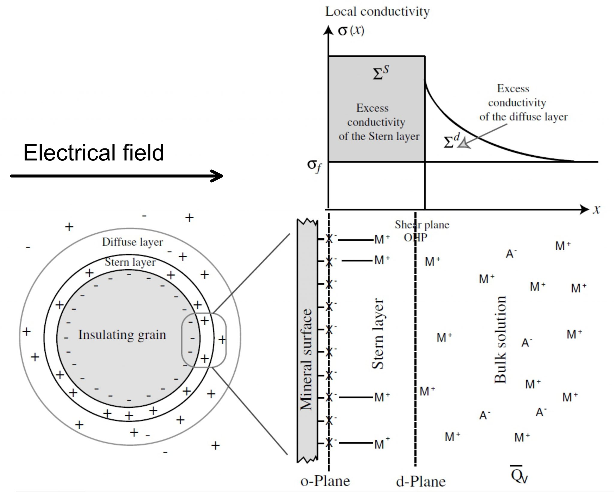
Figure 1. Polarization model of an insulating particle (quartz for example) undergoing an external electrical field applied via the injection current of the induced polarization transmitter. The temporal signal used in induced polarization is the one observed when the external excitation has just been cut off.
Or, in the case of a pyrite or graphitic grain, the particle itself will behave as a dipole which in return modifies the grain surrounding in terms of charge distribution (Figure 2).
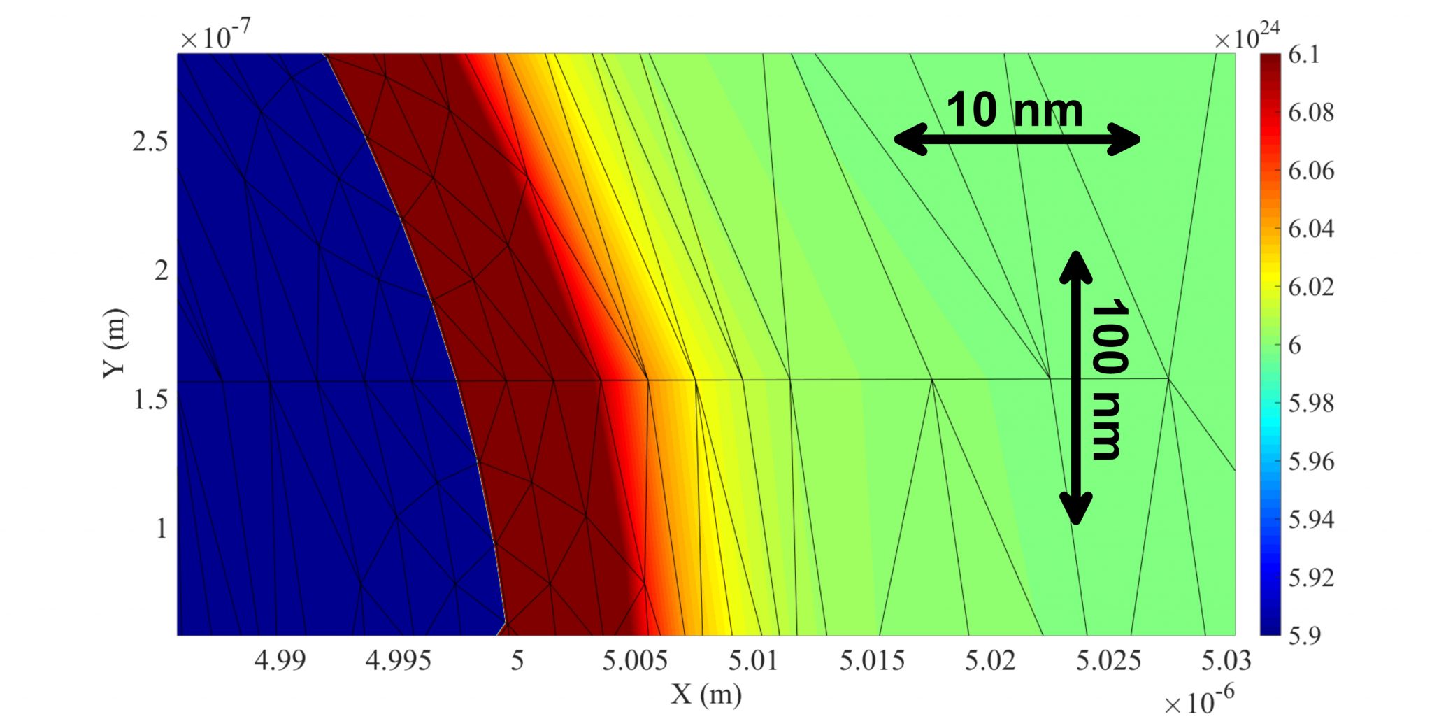
Figure 2. Finite Element modeling with the numerical emerging of the electrical double layer. The grain on the left is made of pyrite and is embedded in a 0.01 mol/l KCl solution. The image shows the anion concentration. This kind of simulation is the starting point for further up-scaling up to the field scale. The modeled equation set is Nernst-Planck coupled with Poisson. Result from Abdulsamad’ thesis, UPMC 2017.
Equipment
The polarization signal is definitely weaker than the main used in conventional electrical prospecting. The natural telluric noise disturbes the polarization signals and then, it must be overrided by the injection magnitude. Hence it is necessary to boost the transmitter power. For this, we use the VIP 500 Iris Instrument power unit (Figure 3, up to 10 A and 3000 V), and a current full wave recorder of the same society (Figure 4).
-
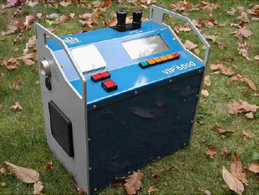
- 3. VIP 5000 (Iris Instrument) : IP powerful transmitter.
-
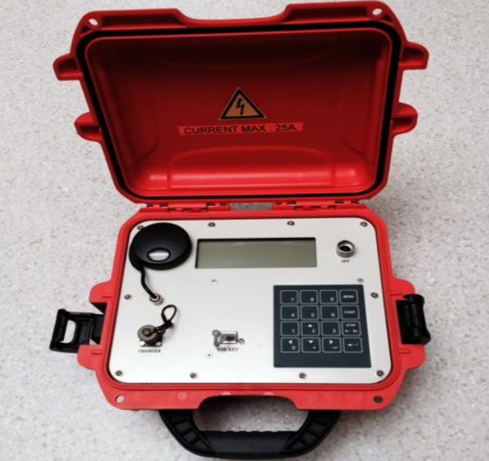
- 4. I-FULL Waver (Iris Instrument) : special IP current recorder.
In parallel, other instruments are used for research purpose especially to complete our knowledge and understanding in the frequency domain (from 0.001Hz to 10 kHz typically: that is the Spectral Induced Polarization already cited).
To obtain a large set of independent measurements, a lot of buried electrodes (saying a hundred) are planted into the ground and addressed by using a multiwire cable. Multiplexed data are then processed to retrieve, through inverse method processes, 2-D or 3-D tomographies. This is called “Electrical Impedance Tomography” (EIT).
Applications
IP can be used in hydrogeology, to map pollutions and/or detect certain mineralizations. Applications may sometimes crossover. For instance at Guidel site (H+ observatory, Brittany, see Figure 5) the hydrogeological information is derived from the absence of IP signal, itself due to the likely oxidation of granit pyrite content.
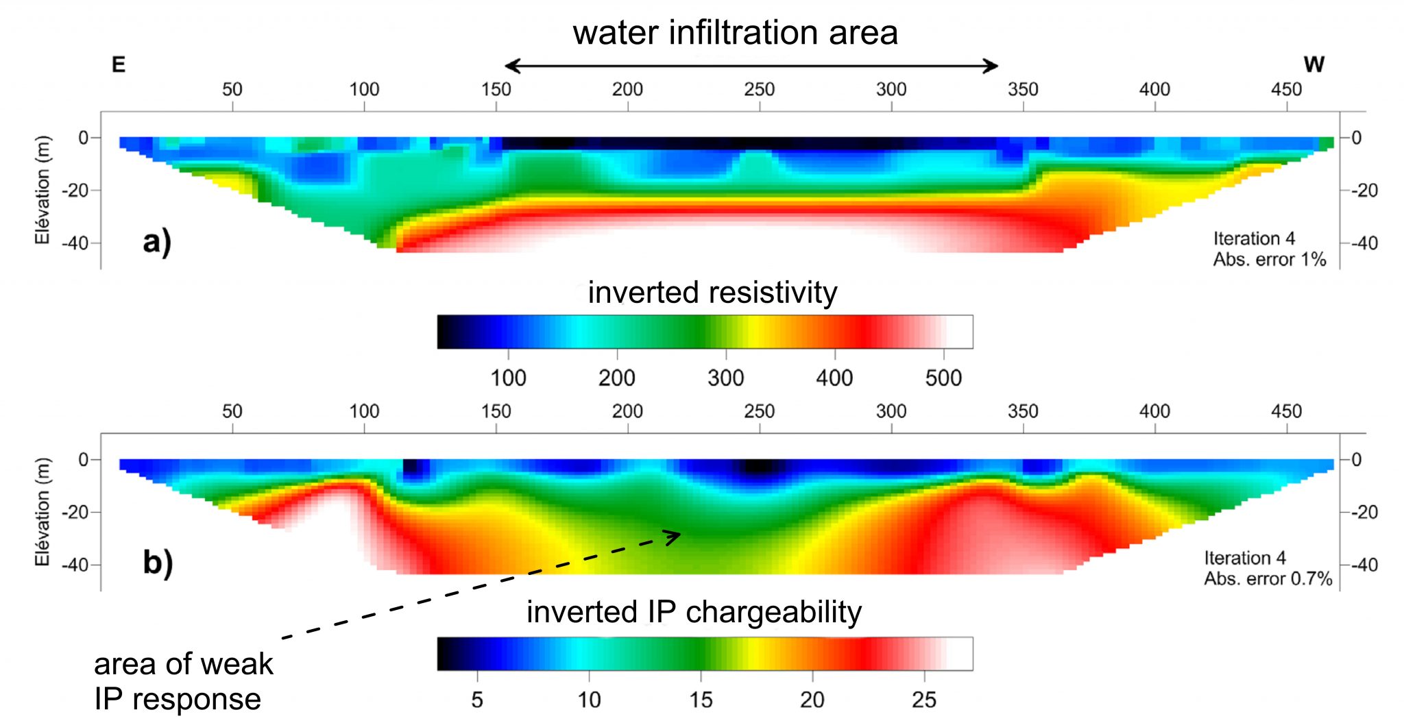
Figure 5: At Guidel site (H+ observatory, Brittany, France) the high chargeability is linked with pyrite preserved in non-weathered granites. In the central zone, pyrite has been oxidized and the chargeability is lower.
Furthermore, IP can be used to assess permeability (Figure 6). This is an updated skill of the method which is very promising. This possibility arises from the fact that the time constant observed in IP is directly linked with the square of particle sizes.
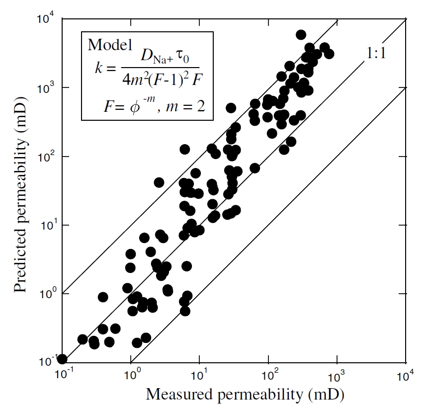
Figure 6: From preliminary results by Revil and Florsch (2010), IF can be used to assess permeability. Nowadays, this idea is increasingly studied and is likely leading to make the method more and more popular.
To finish, let us show an example of IP application to an ancient slag waste deposit, including magnetite particles. Those provide the IP response, which is independent of the resistivity background (Figure 7). Finally the buried heap is delimited with accuracy.
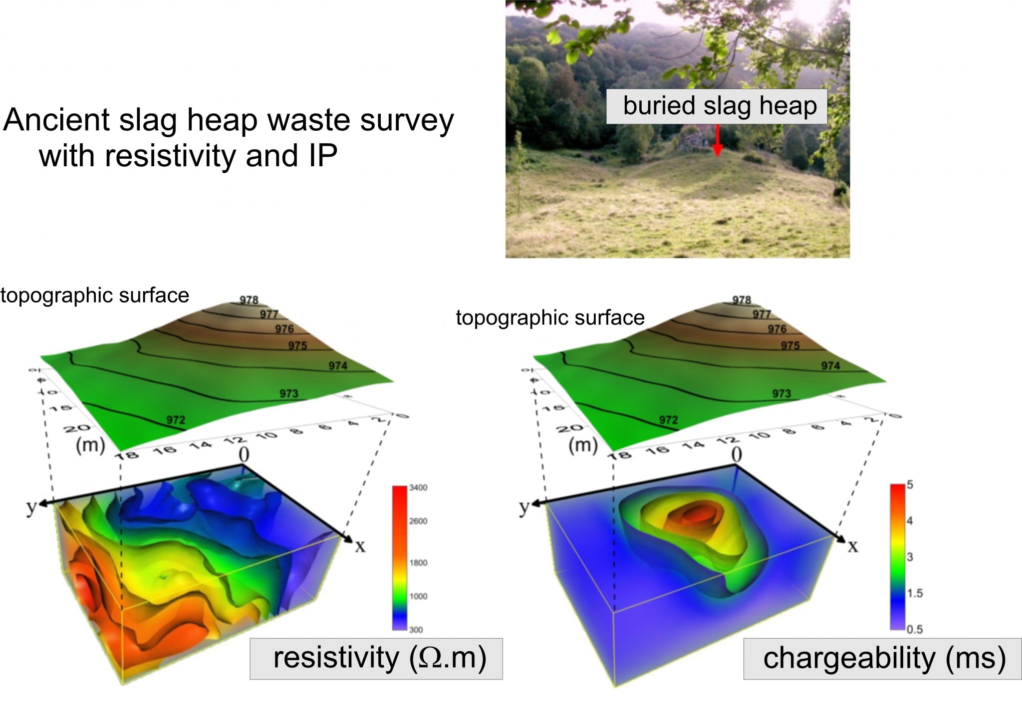
Figure 7: On the mining site of Aulus-les-Bains (Ariège, France), IP permits to map an ancient slag heap, where magnetite particles are responsible of the IP signal. One observes that IP and resistivity are fairly independent.
Finally, IP addresses a physic different from the one relative to resistivity: it is a method in its own right. IP is undergoing a true revival with new environmental applications, which are reflected in a high increase of peer-to-peer journal publications.
WP leaders: Christian Camerlynk and Nicolas Florsh